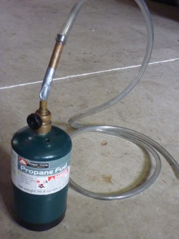
If you suspect you have a vacuum leak on your intake manifolds build yourself a leak detector. Propane works great.
I used a 1# propane tank with a torch on top. Tape up the vent holes and add a length of flexible tube.
Turn the propane on and use the hose to find leaks by moving it around different areas while the bike is idling. RPMs will increase if there is a intake leak. By pulling the hose away and letting the engine slow down and the putting it back up to a suspected area you can pinpoint a leak.
I removed the knee pad and shoved the tube in and around the throttle bodies and sure enough a leak was detected. Off come the fairing side lowers so I can pinpoint the leak. If you don't know how to do this you remove the knee pad (has the fuel gauge in it) the radio and radio box. If you have engine guards the left one has to come off. Then remove all the screws and bolts in the lower fairing. If you have a LT or a RT, a much more comprehensive fairing removal write up by frankenduck is
here.
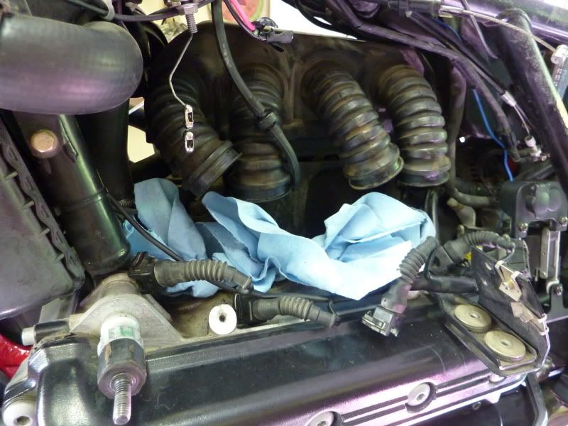
This what it looks like.
After exploring around I kept getting a leak from the rubber bushing ( as BMW calls it) on the #2 intake manifold. But it didn't look any different than the other 3 bushings. Bushings are the thick rubber boot that connects the throttle body to the intake manifold.
The fuel rail is in the way.
Blow out the area with compressed air and clean it up as good as you can before proceeding.
Note: It is recommended to depressurize the fuel system before unhooking the lines. The easiest way to do this is to unhook a fuel line while holding a rag around it to keep the fuel from spraying out. Just keep in mind that it is a pressurized system and will spray a some fuel. Plug the hose ends (if you're not replacing them) with golf tees.
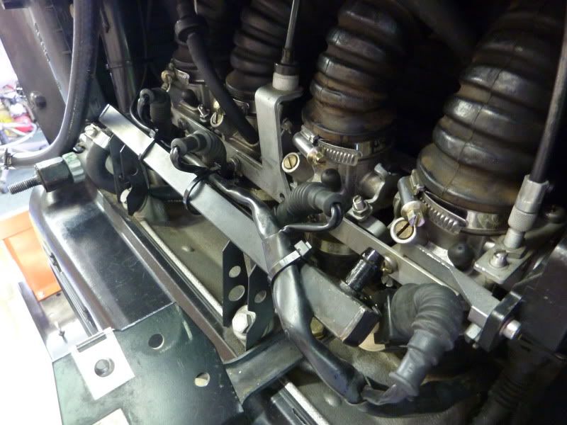
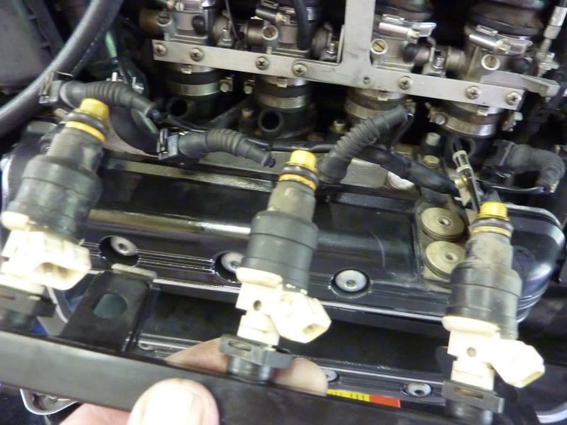
So out it comes. You just unhook connectors and fuel lines. Cut the zip ties on the fuel rail that hold the wiring to the rail so you can get the wiring out of the way. The 2 bolts holding the rail on are the ones in the foreground in the above picture. Then pull gently (yea, right) straight out so you don't damage the injectors.
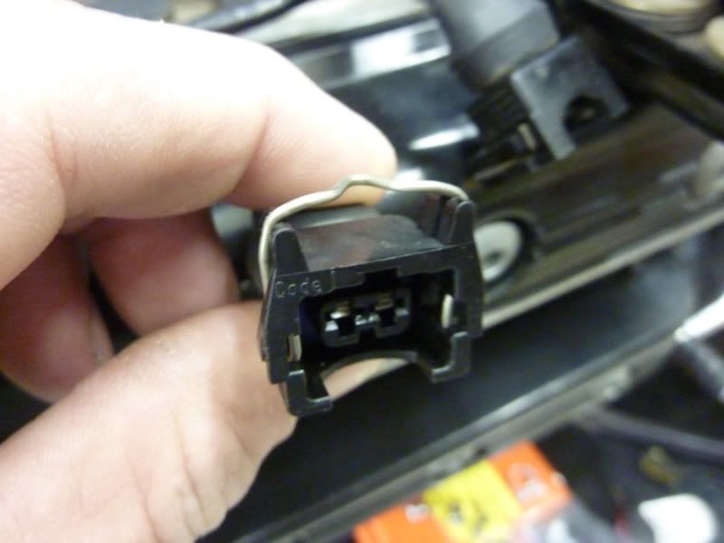
Here's a closeup of the injector connector. Push down on the wire while pulling gently to remove it from the injectors.
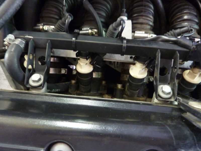
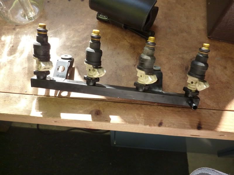
Fuel rail removed from the intake manifold.
Ready to take the injectors out so I can have them cleaned and serviced by
Mr. Injector in Dalton Gardens, ID, about 20 miles from me. If you don't have them serviced by Bill at Mr. Injector then you will need to replace the o-rings before re-installation. Bill will have them ready to install if you use his service.
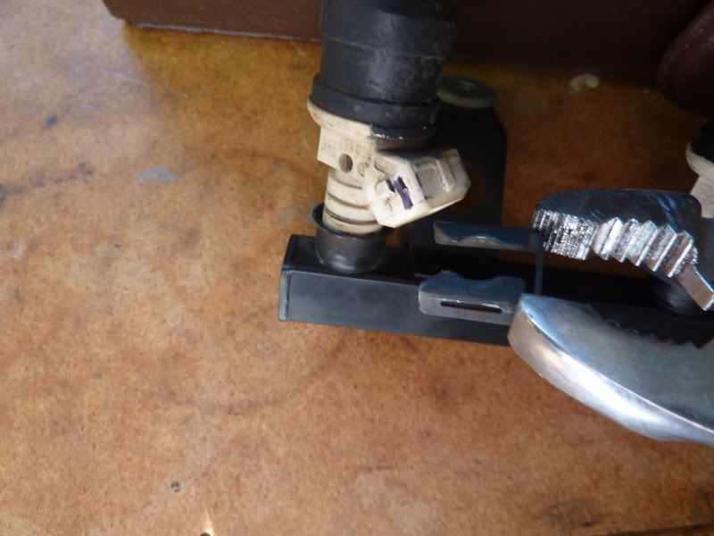
Use a pair of pliers to pull off the retaining clips. I'm holding the clips in the correct orientation so you can see how they came off and I will remember how they go back on the injectors. Clymers recommends marking the injectors so they can be reinstalled in the same order. I don't think it matters if you have them serviced but I marked them anyway with a black felt pen. We'll see if it survives the cleaning process.
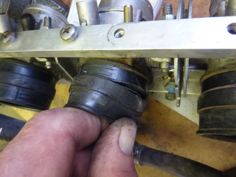
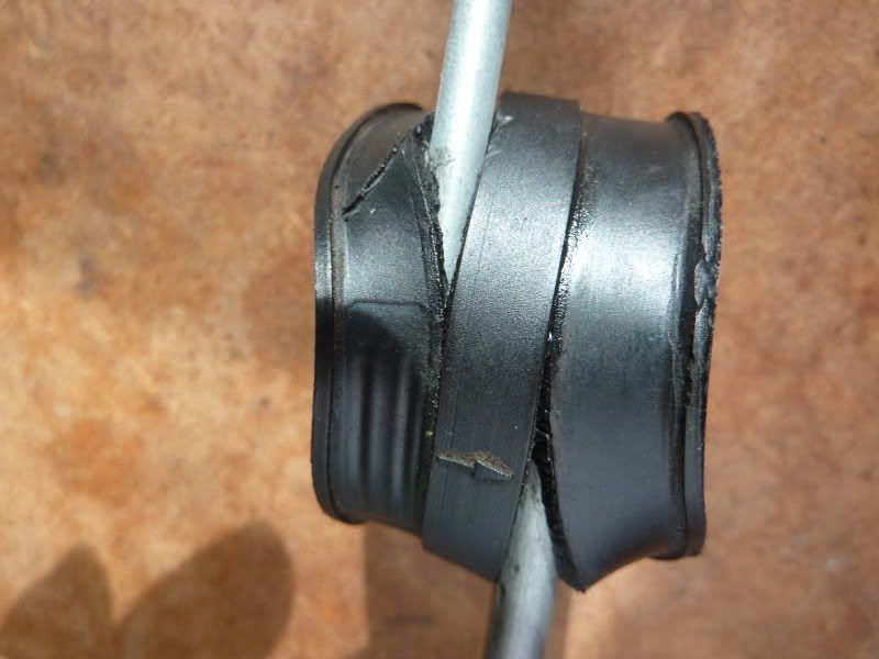
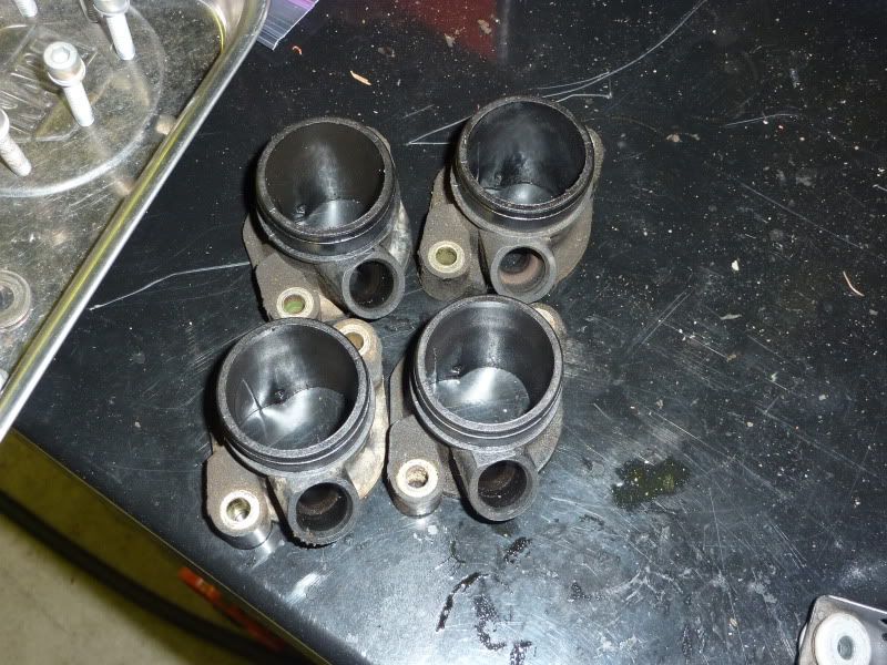
Aha! Torn bushing. The other 3, while not torn completely through, were very close to it right where the clamps connected on each end. That's why I couldn't see any difference in the bushings. I would highly recommend replacing these rubber bits every 15 years or so. I could have done this last winter when I couldn't ride instead of missing a couple of weeks waiting for parts. Fuel lines also. I had a fuel line spring a pinhole leak last summer. There are three. Two come off the bottom of the gas tank, supply and return. Supply runs to the fuel regulator (which is behind the throttle body assembly) and the the third is a short hose that runs from the regulator to the fuel rail.
Note that I've cut off the "one time use" hose clamps and will replace them with good old worm drive stainless clamps. BMW put the "one timers" on one end and worm drives on the other end of the bushings for whatever reason.
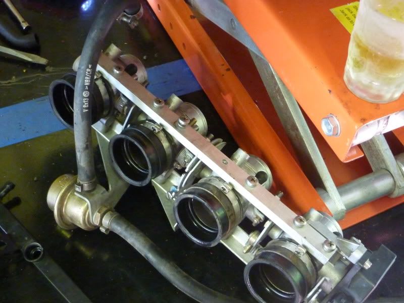
Next comes the throttle bodies themselves. Remove the four hose clamps that hold the bushings to the airbox , throttle cable, idle advance cable (choke), cruise control cable and vacuum line (you've done Duck's cruise, right?). Remove the cables by rotating the throttle rail by hand. You will see a slot for the cable and nipple to come out of the assembly.
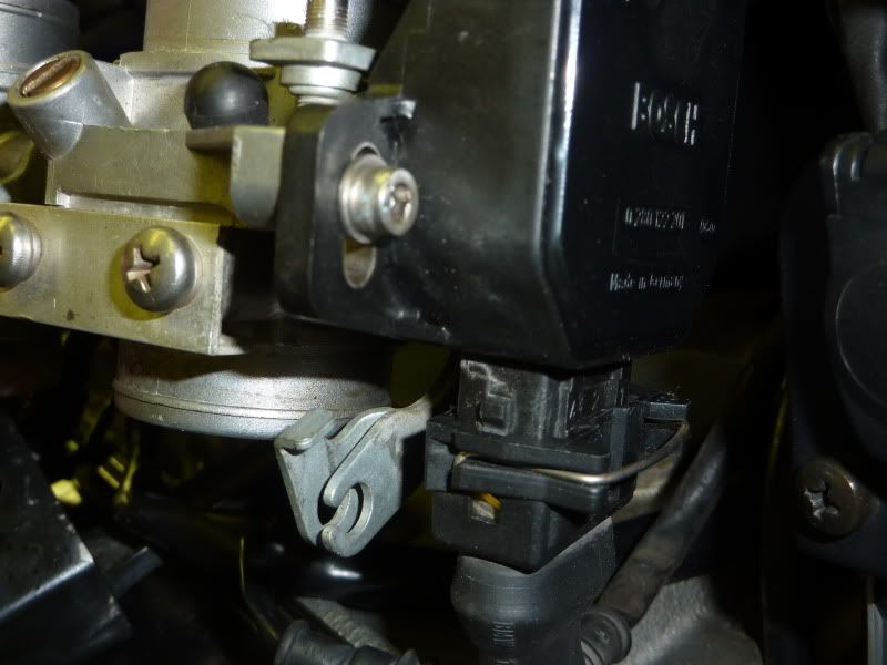
Don't forget to unplug the throttle position sensor located on the right end of the throttle bodies. It has a similar wire clip as the injectors. See below picture.
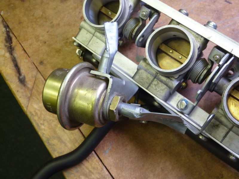
That's the fuel regulator attached to the throttle body assembly by fuel hoses. The shot of whiskey, straight from the freezer, is optional.
If you replace those fuel hoses make sure to cover the holes in the regulator with tape so dirt can't get into it until you reinstall the new lines.
When I get it out it's worse than I thought.
The intake manifolds are held in place with two bolts each and are made of plastic. There is a flexible o-ring under each one which will be dried out. Replace the o-rings for sure and the manifolds at your discretion. I'm going to replace both to be safe.
Here's a shot of the manifolds removed. The bolts are cleaned up in the parts tray to the left.
Heart ripped out of her.
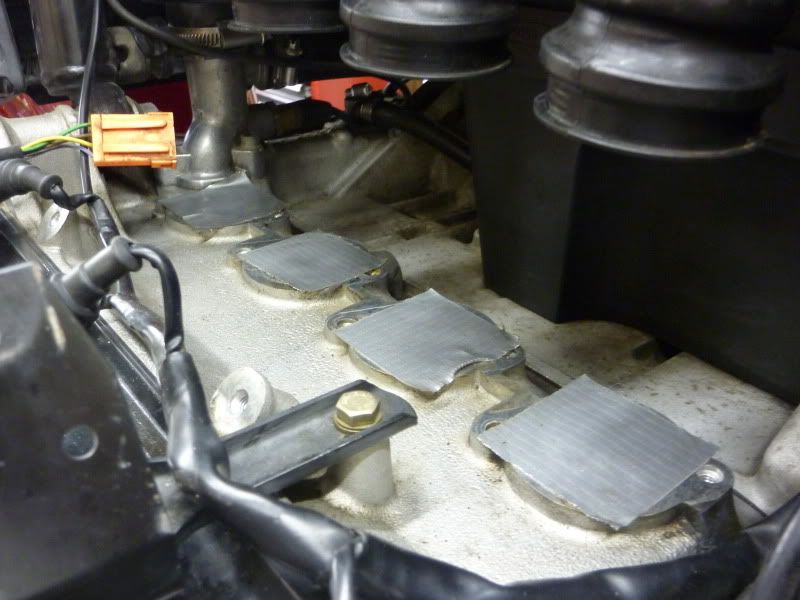
As noted above, you are supposed to clean the area all up before you do any of this which is nearly impossible with all the ch!t in the way so I covered the holes with duct tape and really gave it a thorough cleaning. I used CRC Lectic-Motive from NAPA. Don't spray it on the plastic parts as per the warning label. It just melts the grease away! Then blow it out with your compressed or vacuum the area. You don't want to get anything in the engine. Now it looks like this waiting for her transplant.
Parts on the way:
1. Fuel lines part numbers:
a)13541461494
b)13311461973
c)13311461971
2. Intake manifold part number:
11611461621
3. Bushings (rubber boots) part number:
11611461739
4 .Manifold seals ( O-rings) part number:
11611465169
5. Worm dive stainless steel clamps for fuel lines and bushings
6. Sparkly clean injectors.
All fer now.....I'll update this when all goes back together.
Picked up my cleaned and serviced injectors today The felt pen marks I made on each injector to identify their position did not survive the cleaning process. Bill said, as I suspected, that position doesn't matter after he services them. They all have identical flow now.
He tests them before cleaning.
The pattern was good on two of the injectors and fair on the other two. No leaks detected on any of them.
Flow was:
Before After Increase%
1. 40 41 3
2. 38 41 8
3. 39 41 5
4. 38 41 8
He said that wasn't too bad for a set that had 80K on them but I'm glad I had it done.
Also advises to use plenty of lubrication on the upper and lower o-rings. Motor oil is what he recommends.


